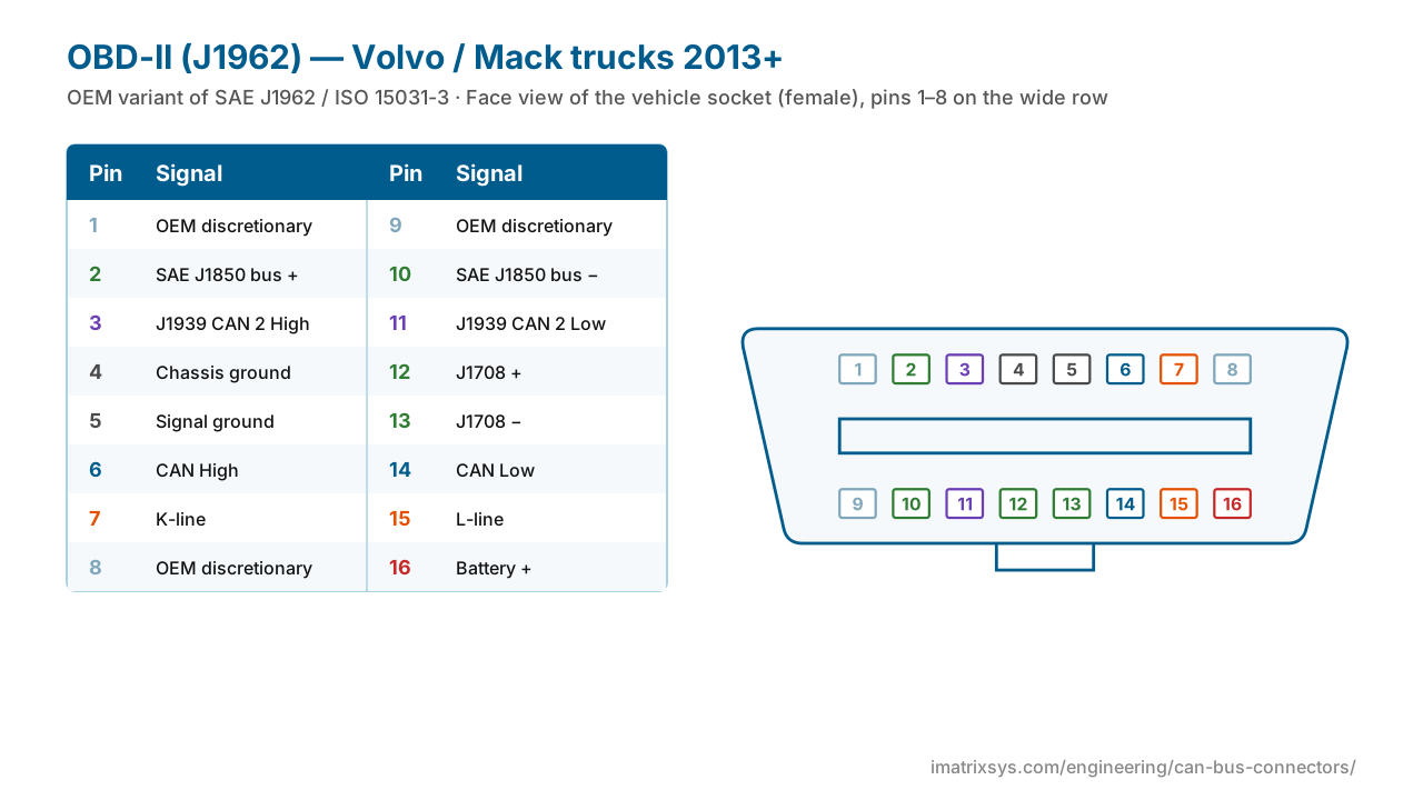
The 16-pin OBD-II connector (SAE J1962) sits under the dashboard of every car and light truck sold in the US since 1996. Here is every pin, which diagnostic protocol uses which pins, the 12 V Type A and 24 V Type B versions, and the Volvo/Mack truck variant.
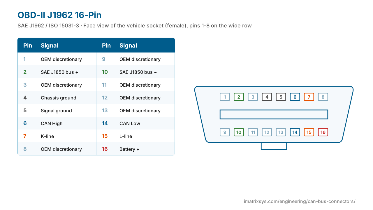
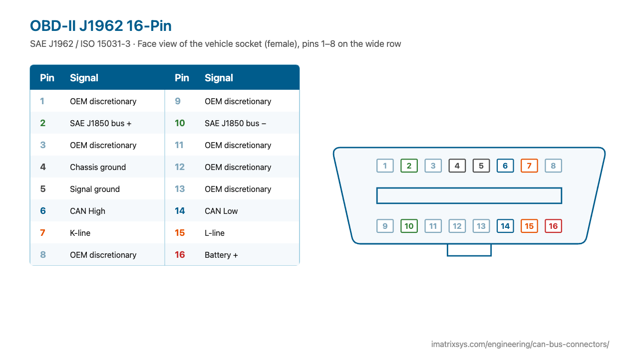
On the vehicle socket the wide row holds pins 1–8 and the narrow row 9–16. CAN High is 6, CAN Low 14, chassis ground 4, signal ground 5 and unswitched battery 16. Grey pins are left to the manufacturer.
Face view of the vehicle socket (female), pins 1–8 on the wide row
| Pin | Signal |
|---|---|
| 1 | Manufacturer discretionary |
| 2 | SAE J1850 bus + |
| 3 | Manufacturer discretionary |
| 4 | Chassis ground |
| 5 | Signal ground |
| 6 | CAN High (ISO 15765-4) |
| 7 | K-line (ISO 9141-2 / 14230-4) |
| 8 | Manufacturer discretionary |
| 9 | Manufacturer discretionary |
| 10 | SAE J1850 bus − — PWM only |
| 11 | Manufacturer discretionary |
| 12 | Manufacturer discretionary |
| 13 | Manufacturer discretionary |
| 14 | CAN Low (ISO 15765-4) |
| 15 | L-line (ISO 9141-2 / 14230-4) — Optional |
| 16 | Battery + (unswitched) — 12 V Type A, 24 V Type B |
| Standard | SAE J1962 / ISO 15031-3 |
|---|---|
| CAN (ISO 15765-4) | 6 High, 14 Low — 250 or 500 kbit/s, mandatory on US cars from MY2008 |
| SAE J1850 | 2 (+) and 10 (−); PWM 41.6 kbit/s, VPW 10.4 kbit/s on pin 2 |
| ISO 9141-2 / KWP2000 | 7 K-line, 15 L-line (optional) |
| Power | 16 battery + (usually live with the key off); 4 chassis ground, 5 signal ground |
| Type A vs Type B | Type A 12 V, continuous centre groove; Type B 24 V, split groove and blue marking |
| Location | Within about 0.6 m (2 ft) of the steering wheel |
California required basic on-board diagnostics from 1988, and the second generation — OBD-II — became mandatory on US cars and light trucks for model year 1996, with a standard 16-pin connector defined in SAE J1962. Europe followed with EOBD for petrol cars from 2001 and diesels from 2004.
OBD-II originally allowed several protocols (J1850, ISO 9141, KWP2000, CAN), which is why so many pins are assigned. Since model year 2008 every US car has used CAN (ISO 15765-4) on pins 6 and 14. ISO 15031-3 added the 24 V Type B connector for commercial vehicles.
Choose any two connectors to get a pin-to-pin wiring diagram, with wire colours, which pins to leave unconnected, and the power and termination warnings that matter. Hover a wire to trace it.
Pick two connectors to draw the wiring. (Needs JavaScript.)
Pin 6 is CAN High and pin 14 is CAN Low (ISO 15765-4).
Pin 16 is battery positive, usually live even with the ignition off. Pin 4 is chassis ground and pin 5 is signal ground.
Type A is for 12 V vehicles and has a continuous centre groove. Type B is for 24 V vehicles, has a split groove and a blue marking. A Type B plug fits both kinds of socket; a Type A plug will not fit a Type B socket.
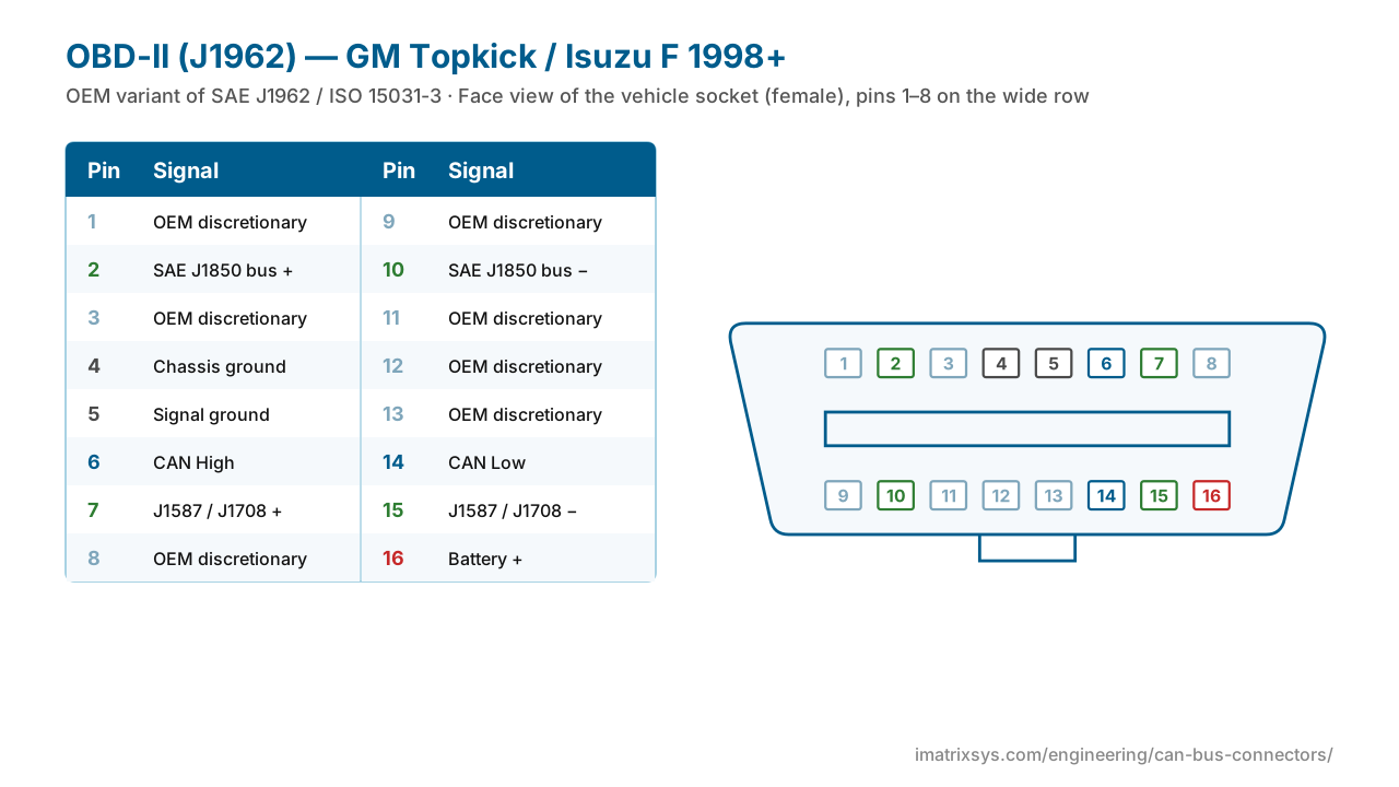
Many vans and medium-duty trucks do, usually with the 24 V Type B. Volvo and Mack heavy trucks have used a 16-pin port since 2013. Most other North American heavy trucks use the 9-pin J1939 connector.
J1962 makes pin 16 unswitched battery so tools work without the ignition on. Devices left plugged in can therefore drain the battery.
CAN uses 6 and 14 (every US car from 2008). J1850 uses 2 and 10. ISO 9141 and KWP2000 use 7 (K-line) and sometimes 15 (L-line).
Sources: Wikipedia: On-board diagnostics; Wikipedia: Data link connector; CSS Electronics: OBD2 explained; NI: CAN OBD-II cable specification; Drew Technologies: Industry Connectors Reference (rev 1.5); CSS Electronics: OBD2 to DB9 cable pinout.
Last reviewed 2026-10-27. Pin assignments follow SAE J1962 / ISO 15031-3; OEM variants are noted where we could verify them. Spotted an error? Tell us.
iMatrix designs and builds CAN, J1939 and OBD-II harnesses for OEMs and fleets, and our FleetConnect telematics devices plug straight into the 9-pin and OBD-II ports. Tell us the two ends and the quantity.