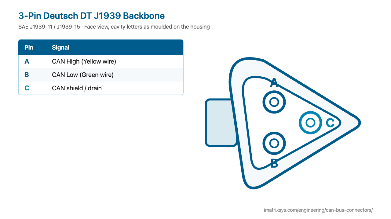
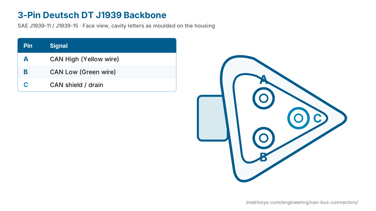
The small triangular 3-pin Deutsch DT connector joins the J1939 backbone, its tees, stubs and the 120 Ω terminator plugs inside trucks and machines. It carries only the CAN pair and the shield — no power, no ground.
A is CAN High (yellow wire), B CAN Low (green) and C the shield drain on shielded J1939-11 networks.
Face view, cavity letters as moulded on the housing
| Pin | Signal |
|---|---|
| A | CAN High — Yellow wire |
| B | CAN Low — Green wire |
| C | CAN shield / drain — J1939-11; often unused on J1939-15 |
| Standards | SAE J1939-11 (shielded) / J1939-15 (unshielded) / J1939-14 (500 kbit/s) |
|---|---|
| Housings | DT04-3P receptacle (pins), DT06-3S plug (sockets) |
| Pins | A CAN High (yellow), B CAN Low (green), C shield |
| Terminators | 120 Ω across A–B, e.g. AT06-3S-RJ120 (Amphenol AT series) |
| J1939-11 limits | 40 m backbone, 30 nodes, stubs up to 1 m |
| Power / ground | None — supply the device ground separately |
SAE started work on J1939 in 1985 and published the first parts, including the shielded J1939-11 physical layer, in 1994. J1939-11 wires the backbone with shielded twisted pair — yellow CAN High, green CAN Low and a drain — which is what the third pin of this connector is for.
J1939-15 (2003) added a cheaper unshielded layer with longer stubs, and J1939-14 (2011) a 500 kbit/s one. The same compact Deutsch DT 3-way connector serves all of them on the backbone.
Add a device through a DT tee and keep its stub short. Do not remove a terminator to plug a device in unless that device then terminates the bus, and never add a third terminator.
Choose any two connectors to get a pin-to-pin wiring diagram, with wire colours, which pins to leave unconnected, and the power and termination warnings that matter. Hover a wire to trace it.
Pick two connectors to draw the wiring. (Needs JavaScript.)
A is CAN High (yellow), B is CAN Low (green) and C is the shield or drain.
With the key off, measure across A and B. An intact backbone reads about 60 Ω; a single terminator plug on the bench reads about 120 Ω.
No. Only the two ends of the backbone are terminated. A third terminator drops the reading to about 40 Ω and causes communication errors.
Both run at 250 kbit/s. J1939-11 uses shielded twisted pair with a drain on pin C; J1939-15 uses unshielded twisted pair and allows longer stubs.
No. It carries only CAN High, CAN Low and the shield. A device on the backbone needs its own ground connection.
Sources: Drew Technologies: Industry Connectors Reference (rev 1.5); Allison J1939 communication link notes; FCAR: 3-pin J1939 jumper; Amphenol AT06-3S-RJ120 terminator; Kvaser: J1939 standards overview; SAE J1939-15 (abstract); SAE J1939-14 (abstract); CSS Electronics: J1939 explained.
Last reviewed 2026-10-27. Pin assignments follow SAE J1939-11 / J1939-15; OEM variants are noted where we could verify them. Spotted an error? Tell us.
iMatrix designs and builds CAN, J1939 and OBD-II harnesses for OEMs and fleets, and our FleetConnect telematics devices plug straight into the 9-pin and OBD-II ports. Tell us the two ends and the quantity.