ISOBUS (ISO 11783) lets any certified implement work with any tractor and terminal. The heart of it is the 9-pin breakaway connector at the hitch, which hands the implement both its electrical power and the CAN bus — and switches the bus termination over to the implement when it is plugged in.
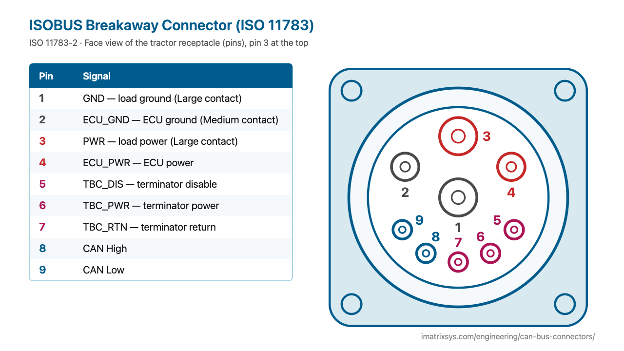
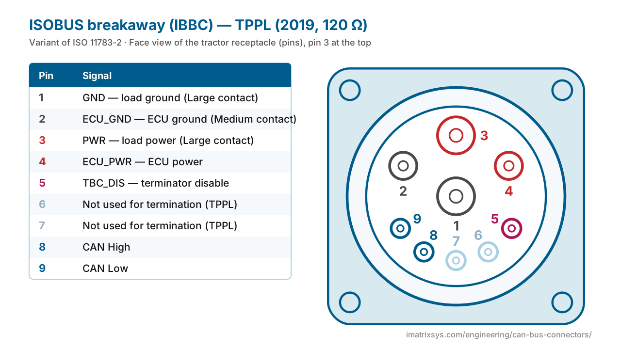
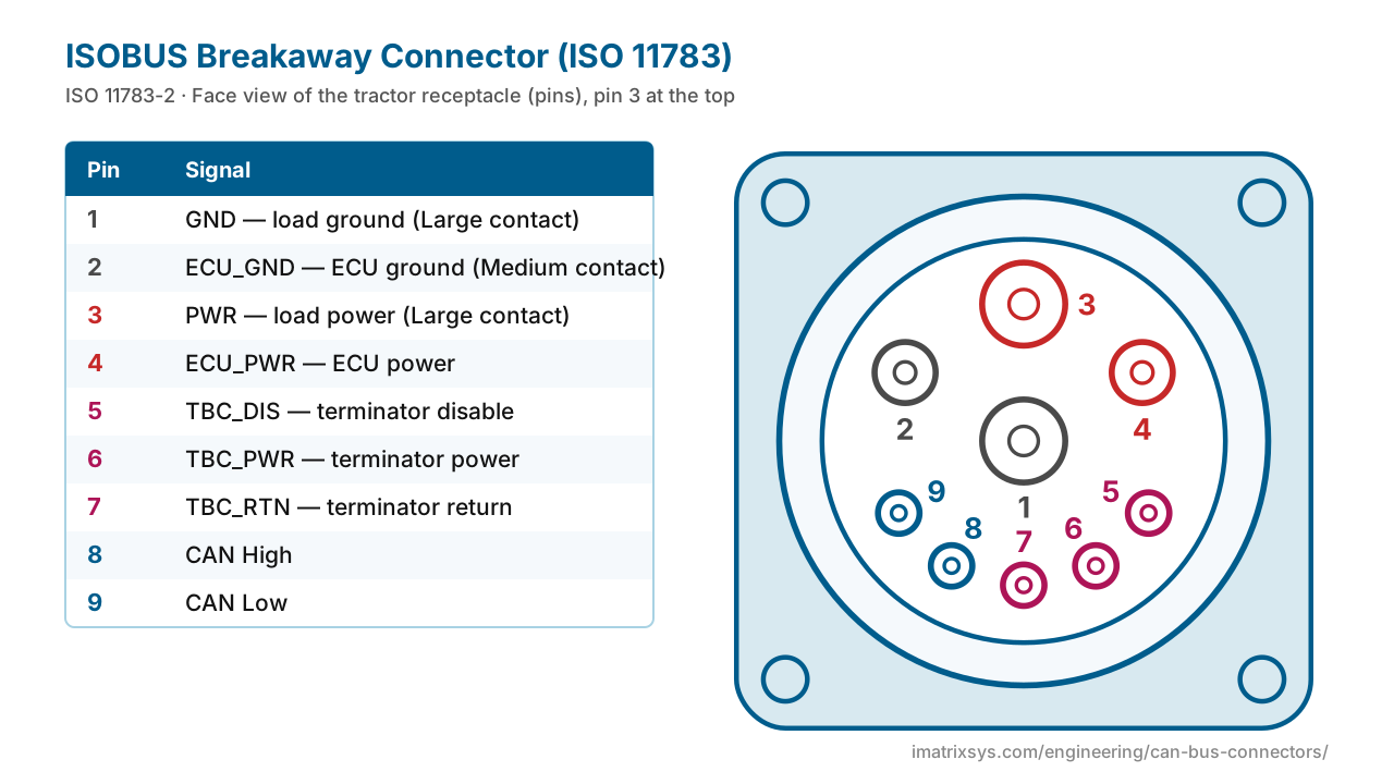
Pin 1 in the centre and pin 3 at the top are the large power contacts (ground and power for heavy loads); 2 and 4 are clean power for the implement’s ECUs; 5–7 serve the bus terminators; 8 and 9 are CAN High and CAN Low. Switch to the implement plug for the mirror image, or to the 2019 twisted-pair (TPPL) version.
Face view of the tractor receptacle (pins), pin 3 at the top
| Pin | Signal |
|---|---|
| 1 | GND — load ground — Large contact |
| 2 | ECU_GND — ECU ground — Medium contact |
| 3 | PWR — load power — Large contact |
| 4 | ECU_PWR — ECU power — Medium; bridged to pin 5 in the implement plug |
| 5 | TBC_DIS — terminator disable — Used only inside the connectors |
| 6 | TBC_PWR — terminator power |
| 7 | TBC_RTN — terminator return |
| 8 | CAN High |
| 9 | CAN Low |
| Standard | ISO 11783-2 (editions 2002, 2012, 2019) |
|---|---|
| Bit rate | 250 kbit/s — there is no faster CAN ISOBUS |
| Network | Up to 30 ECUs and 40 m per segment; unshielded twisted quad (CAN_H, CAN_L, TBC_PWR, TBC_RTN) |
| Contacts | 2 large (1, 3), 2 medium (2, 4), 5 small (5–9); connector rated 60 A |
| Power wires | 6, 10 or 16 mm² on the large PWR / GND contacts |
| Genders | Tractor receptacle with pins; implement plug (IBBP) with sockets |
| Termination | Active terminating bias circuits (TBC); 120 Ω on TPPL (2019) |
ISOBUS grew out of Germany’s LBS agricultural bus (DIN 9684), standardised from 1991, and SAE J1939, on which it builds its 250 kbit/s CAN layers. It was first shown at Agritechnica in 2001, and ISO 11783 was published in parts from 2002 onward; Part 2, the physical layer with the hitch connector, appeared in 2002, with new editions in 2012 and 2019. The 2019 edition added a twisted-pair physical layer (TPPL) based on SAE J1939-15, which uses plain 120 Ω termination and works with older machines in both directions.
In 2008 the manufacturers founded the Agricultural Industry Electronics Foundation (AEF), which tests and certifies ISOBUS by functionality — Universal Terminal (UT), Task Controller (TC-BAS, TC-GEO, TC-SC section control), auxiliary controls (AUX-N), Tractor ECU (TECU) and Tractor Implement Management (TIM). Two machines work together only on the functionalities both support. AEF’s “High Speed ISOBUS” is a separate Ethernet network, not a faster CAN.
A plain CAN bus is terminated by a 120 Ω resistor at each end. ISOBUS instead uses terminating bias circuits (TBC) that sit outside the ECUs and are powered over their own pair, TBC_PWR and TBC_RTN, so the bus stays correctly terminated whenever an implement or ECU is unplugged. The tractor’s hitch socket contains a TBC. Inside the implement plug, pin 4 (ECU_PWR) is bridged to pin 5 (TBC_DIS): when the plug goes in, the socket switches its own terminator out, and the termination moves to the far end of the implement’s bus. Unplug the implement and the socket reconnects its terminator automatically.
Makers colour-code the sockets: black inserts are active (they power the terminators; one per tractor network) and grey are passive, used at the front of the tractor or on pass-through implements.
Terminals, joysticks and other in-cab devices join the bus through a 9-pin TE CPC connector in the cab, descended from the LBS socket. The bus loops through it, so CAN High and CAN Low each have an in and an out pin:
| Pin | Signal | Pin | Signal |
|---|---|---|---|
| 1 | Not used for signals | 6 | TBC_PWR |
| 2 | CAN Low in | 7 | ECU_PWR |
| 3 | CAN Low out | 8 | TBC_RTN |
| 4 | CAN High in | 9 | ECU_GND |
| 5 | CAN High out |
Where a bus ends away from a socket, an in-line 6-pin terminator plug carries the TBC: A ECU_PWR, B TBC_PWR, C ECU_GND, D TBC_RTN, E CAN High, F CAN Low.
ISOBUS machines use the same 9-pin Deutsch diagnostic connector as J1939 trucks. The tractor’s own J1939 bus stays on pins C and D; on ISOBUS tractors the implement bus is on pins H and J. Choose the “ISOBUS tractor” pin-out on the 9-pin page to see it.
Choose any two connectors to get a pin-to-pin wiring diagram, with wire colours, which pins to leave unconnected, and the power and termination warnings that matter. Hover a wire to trace it.
Pick two connectors to draw the wiring. (Needs JavaScript.)
The 9-pin breakaway connector at the back of the tractor: 1 GND, 2 ECU_GND, 3 PWR, 4 ECU_PWR, 5 TBC_DIS, 6 TBC_PWR, 7 TBC_RTN, 8 CAN_H, 9 CAN_L. Pins 1 and 3 are the large high-current contacts.
The tractor’s receptacle has male pins and the implement plug (IBBP) has female sockets. Inside the implement plug, pin 4 (ECU_PWR) is bridged to pin 5 (TBC_DIS), which tells the tractor socket to switch out its own terminator.
A terminating bias circuit: an active terminator that sets the CAN lines’ bias and terminates the bus, powered over TBC_PWR and TBC_RTN. ISO 11783-2 places it outside the ECUs so the bus stays terminated when anything is unplugged. The 2019 twisted-pair variant (TPPL) uses a plain 120 Ω resistor instead.
ISOBUS (ISO 11783) is built on J1939’s 250 kbit/s CAN with 29-bit identifiers, and adds agricultural functions such as the universal terminal, task controller and file server. Its physical layer differs too: a twisted quad with active terminators and a breakaway hitch connector.
A 9-pin TE CPC connector: 1 not used for signals, 2 CAN_L in, 3 CAN_L out, 4 CAN_H in, 5 CAN_H out, 6 TBC_PWR, 7 ECU_PWR, 8 TBC_RTN, 9 ECU_GND.
Yes. ISOBUS machines use the same 9-pin Deutsch connector: the tractor’s J1939 bus is on C and D, and the ISOBUS implement bus on H and J.
Up to 40 m per segment with at most 30 ECUs, at a fixed 250 kbit/s.
Sources: ISO 11783-2:2019 sample pages; Kramp: ISOBUS connection (ISO 11783-2 tables); TE drawing 0425-014-2400: HD30 shell 24 contact arrangements; Erich Jaeger: ISOBUS connectors for agricultural machinery; Erich Jaeger: 9-pin ISOBUS plug; Amphenol: ISOBUS IBBC connectors; AEF: TPPL; AEF: High Speed ISOBUS; AvMap: ISOBUS retrofit cable guide; CSS Electronics: ISOBUS introduction; DLG TestService: AEF ISOBUS conformance test; Wikipedia (de): ISOBUS.
Last reviewed 2026-10-28. Pin assignments follow ISO 11783-2; OEM variants are noted where we could verify them. Spotted an error? Tell us.
iMatrix designs and builds CAN, J1939 and OBD-II harnesses for OEMs and fleets, and our FleetConnect telematics devices plug straight into the 9-pin and OBD-II ports. Tell us the two ends and the quantity.