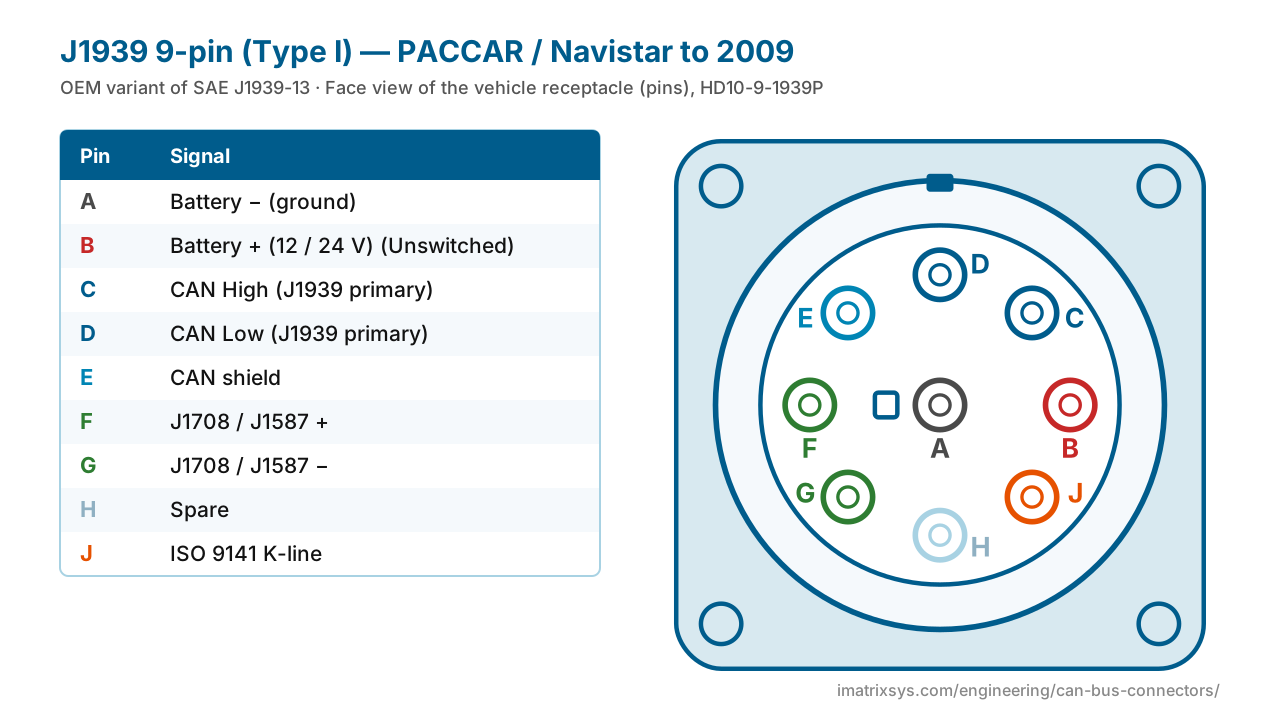
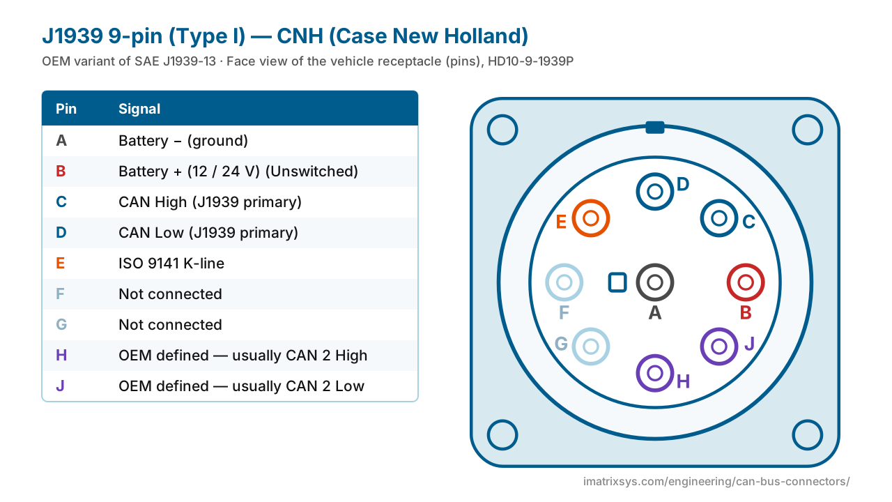
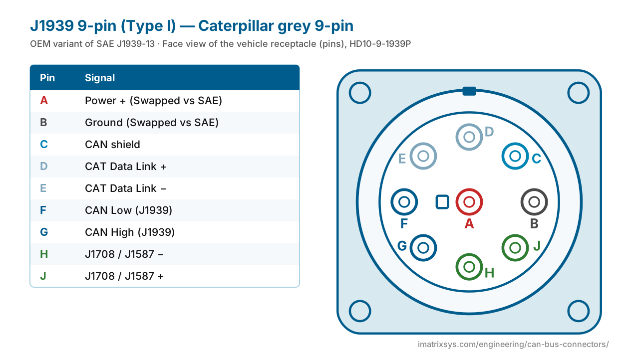
The round 9-pin Deutsch HD10 connector is the diagnostic port on North American heavy trucks, buses and much off-highway equipment. This is the black Type I version defined by SAE J1939-13 — with the PACCAR, Navistar, CNH and Caterpillar variants that catch technicians out.
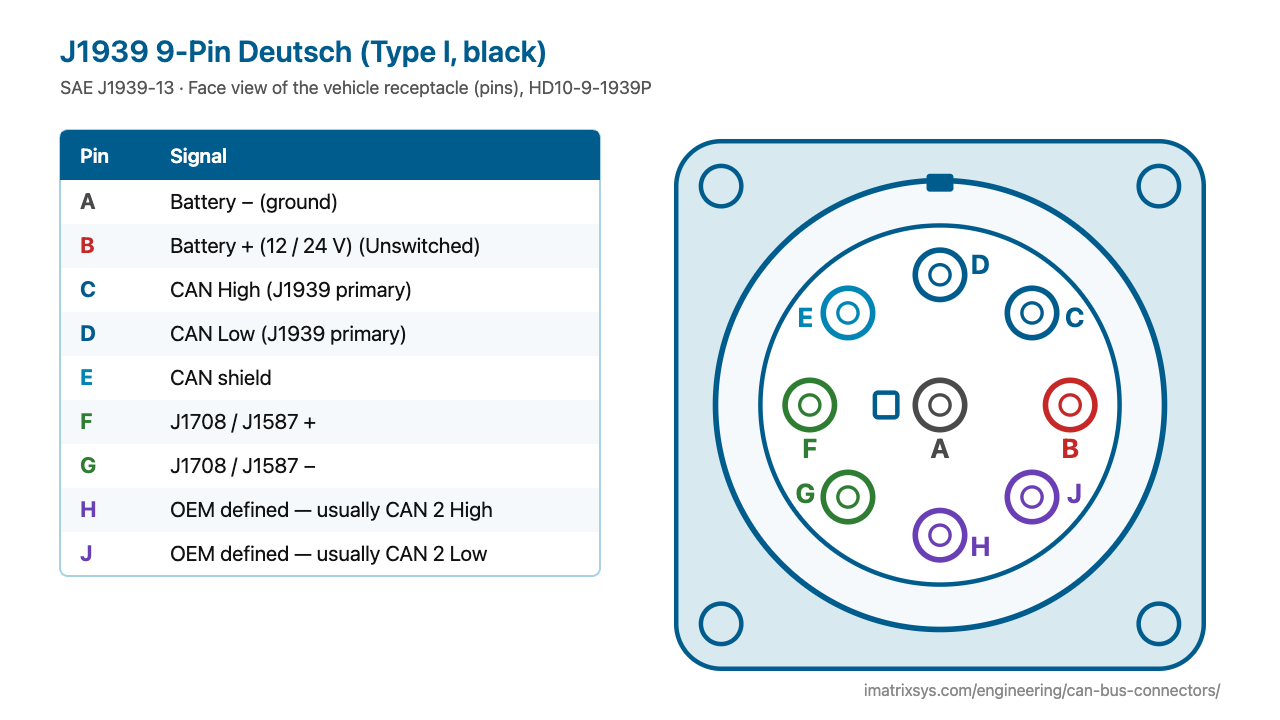
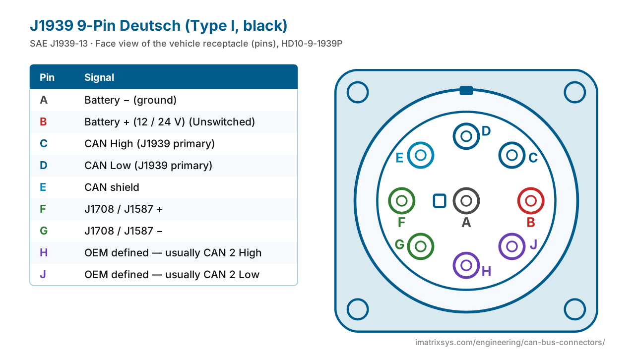
Pin A sits in the centre with a polarising key beside it; the other eight pins form a ring. CAN High and CAN Low are on C and D, battery on A (ground) and B (positive), and the letter I is skipped. Use the switch to see how OEMs change pins E–J.
Face view of the vehicle receptacle (pins), HD10-9-1939P
| Pin | Signal |
|---|---|
| A | Battery − (ground) |
| B | Battery + (12 / 24 V) — Unswitched |
| C | CAN High (J1939 primary) |
| D | CAN Low (J1939 primary) |
| E | CAN shield |
| F | J1708 / J1587 + |
| G | J1708 / J1587 − |
| H | OEM defined — usually CAN 2 High |
| J | OEM defined — usually CAN 2 Low |
| Standard | SAE J1939-13 (first issued 1999, current revision 2024) |
|---|---|
| Vehicle side | HD10-9-1939P receptacle — pins, black |
| Tool side | HD16-9-1939S plug — sockets, threaded coupling ring |
| Contacts | Size 16, 13 A |
| Primary CAN | C (High) / D (Low), 250 kbit/s on Type I |
| Power | B = unswitched battery, 12 V or 24 V; A = ground |
| Termination | None in the connector or the tool — it is a stub |
| Successor | Type II (green), 250/500 kbit/s |
Until the mid-1990s every heavy-truck maker had its own diagnostic plug. The industry first standardised on a 6-pin Deutsch for the older J1708/J1587 data link, then — as J1939 CAN took over from about 2001 — moved to the 9-pin Deutsch defined in SAE J1939-13, first issued in July 1999.
The 9-pin was a transition connector by design: it carried the new J1939 CAN on C and D while keeping the legacy J1708 pair on F and G, so one port served old and new tools. Pins H and J were left to the OEM, and most now use them for a second CAN network.
Choose any two connectors to get a pin-to-pin wiring diagram, with wire colours, which pins to leave unconnected, and the power and termination warnings that matter. Hover a wire to trace it.
Pick two connectors to draw the wiring. (Needs JavaScript.)
A battery ground, B battery positive (unswitched, 12 or 24 V), C CAN High, D CAN Low, E CAN shield, F J1708/J1587 +, G J1708/J1587 −, H and J OEM defined (usually a second CAN). There is no pin I.
Pin A (ground) is the centre pin, next to the polarising key. Looking at the vehicle receptacle, D is at the top and the ring runs clockwise C, B, J, H, G, F, E.
Pin B is unswitched battery at the vehicle’s system voltage, so it is 24 V on 24 V vehicles. Check that anything powered from the port accepts that range.
SAE J1939-13 leaves them to the manufacturer. Most trucks put a second CAN network there; some older PACCAR and Navistar trucks put ISO 9141 K-line on J instead.
Manufacturers only populate the circuits they use, so empty F, G, H or J cavities are normal.
No. A green (Type II) cable fits both black and green ports, but a black Type I cable will not go into a green Type II port.
Sources: Drew Technologies: Industry Connectors Reference (rev 1.5); Copperhill: SAE J1939 9-pin to DB9; PEAK-System: PCAN-Cable J1939; Intrepid: J1939 Type II to DB9 cable; CSS Electronics: J1939 explained; Wikipedia: SAE J1587; SAE J1939-13 (abstract); Drew Technologies PACCAR / Navistar K-line cable; CSS Electronics: Caterpillar 9-pin to DB9.
Last reviewed 2026-10-27. Pin assignments follow SAE J1939-13; OEM variants are noted where we could verify them. Spotted an error? Tell us.
iMatrix designs and builds CAN, J1939 and OBD-II harnesses for OEMs and fleets, and our FleetConnect telematics devices plug straight into the 9-pin and OBD-II ports. Tell us the two ends and the quantity.